More actions
No edit summary |
|||
| (2 intermediate revisions by the same user not shown) | |||
| Line 48: | Line 48: | ||
= Week 2 = | = Week 2 = | ||
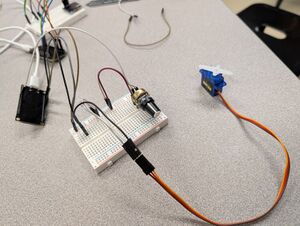
[[File:mfs25s_servowiring.jpg|thumb|Wiring setup with a servo and potentiometer]] | |||
== Getting Started with Servos == | == Getting Started with Servos == | ||
# Download the ESP32Servo Library from Library Manager in Arduino IDE. | # Download the ESP32Servo Library from Library Manager in Arduino IDE. | ||
# Use this code to start | # Use this code to start | ||
#*<syntaxhighlight lang="c++" line> | #*<syntaxhighlight lang="c++" line> | ||
#include <ESP32Servo.h> | #include <ESP32Servo.h> | ||
Servo | #define POT 14 | ||
Servo servo; | |||
int pos = 0; | int pos = 0; // variable to store the servo position | ||
void setup() { | void setup() { | ||
servo.attach(5); // attaches the servo on pin 9 to the Servo object | |||
pinMode(POT, INPUT); | |||
Serial.begin(9600); | |||
} | } | ||
void loop() { | void loop() { | ||
int pot_value = analogRead(POT); | |||
Serial.println(pot_value); | |||
int servopos = map(pot_value, 0, 4095, 0, 180); | |||
servo.write(servopos); | |||
delay(15); | |||
} | } | ||
</syntaxhighlight> | </syntaxhighlight> | ||
| Line 77: | Line 84: | ||
* Use a potentiometer to control the speed of the sweep | * Use a potentiometer to control the speed of the sweep | ||
* Synchronize LEDs to do something with the LED | * Synchronize LEDs to do something with the LED | ||
= Week 3 = | = Week 3 = | ||
= Week 4 = | = Week 4 = | ||
Latest revision as of 16:39, 13 February 2025
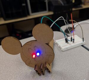
This Spring, an adult cohort is exploring animatronics. We'll post helpful resources and our progress along the way here.
Week 1


Resources
- Arduino IDE
- Install ESP32 boards in Arduino
- Starter Code
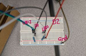
#define BLUE_LED 2  // LED connected to D2
#define RED_LED 4  // LED connected to D4

void setup() {
  // Initialize the LED pins as outputs
  pinMode(BLUE_LED, OUTPUT);
  pinMode(RED_LED, OUTPUT);
}

void loop() {
  digitalWrite(BLUE_LED, HIGH);
  digitalWrite(RED_LED, HIGH);
  delay(100);
  digitalWrite(BLUE_LED, LOW);
  digitalWrite(RED_LED, LOW);
  delay(100);
}
Extensions
The challenges were generated using AI (Google's Gemini, but Chat-GPT would have produced something similar). If something looks too challenging, ask AI to explain how you'd go about coding it and see what makes sense!
Basic Blinking and Delays
- The Single Winking Eye: One LED acts as an eye. It stays on (open) for a longer duration, then flashes quickly (winks) for a shorter duration. This practices basic on/off states and different delay values. Vary the "open" and "wink" times.
- Dual Winking Eyes (Asymmetrical): Two LEDs, each acting as an eye, wink independently but with different timings. One eye might wink more frequently than the other. This introduces the concept of controlling multiple outputs concurrently but with individual timing.
- The Blinking Eyelid: One LED is the "eyelid." It starts on (closed), then turns off briefly (opens the eye), and then back on (closes). Experiment with the open time to simulate different eyelid speeds.
Introducing Sequences and Patterns
- The Sequential Gaze: Three LEDs arranged in a row. Turn them on one at a time, creating the illusion of a gaze moving from left to right or vice versa. This introduces the concept of sequential control and using loops.
- The Breathing LED: One LED simulates breathing. It gradually increases in brightness (inhale) and then gradually decreases (exhale). This introduces analog output control (PWM) and smoother transitions. You can do this with a single LED using PWM.
- The Heartbeat: One LED mimics a heartbeat. It pulses with a distinct rhythm, simulating a heartbeat sound. This combines timing with a specific pattern.
Adding Complexity
- The Reacting Eye: One LED is an eye. It's normally "asleep" (dimly lit). When a button is pressed (or some other simple input), it "wakes up" (becomes brightly lit) for a short period and then returns to the dim state. This introduces basic input and event-driven behavior.
- The Scanning Eyes: Two LEDs represent eyes scanning back and forth. They illuminate one at a time, creating a scanning effect. You can add a third LED in the center that lights up when the "eyes" meet in the middle.
- The Fading Emotion: One LED represents an emotion. It fades in slowly to full brightness (e.g., surprise) and then fades out slowly (e.g., returning to normal). This reinforces PWM and introduces more complex fading patterns.
Week 2

Getting Started with Servos
- Download the ESP32Servo Library from Library Manager in Arduino IDE.
- Use this code to start
#include <ESP32Servo.h>

#define POT 14

Servo servo;

int pos = 0;    // variable to store the servo position

void setup() {
  servo.attach(5);  // attaches the servo on pin 9 to the Servo object
  pinMode(POT, INPUT);
  Serial.begin(9600);
}

void loop() {
  int pot_value = analogRead(POT);
  Serial.println(pot_value);
  int servopos = map(pot_value, 0, 4095, 0, 180);
  servo.write(servopos);
  delay(15);
}
Challenges
- Make the servo sweep back down gradually (instead of the sudden jump)
- Use a potentiometer to control the speed of the sweep
- Synchronize LEDs to do something with the LED
